This post explains the I2C peripheral working for STM32F4 Series of micro controllers by ST microelectronics. I am using STM32F4 discovery board to perform all the experiments. I2C is a very commonly used inter ICs communication protocol in embedded systems. I2C was originally formulated by Philips semiconductor for communication between chips on a TV circuit board, but now a days hundred of chips uses I2C to communicate with each other. This post does not aim to explain I2C protocol, for more details on I2C Download this application note by NXP.
Just for the sake of demonstration of I2C peripheral in STM32F4xx I am going to use 24C512 EEPROM chip, which uses I2C protocol to communicate with Host controller (STM32F4xx in this case). Figure below shows the pin diagram of EEPROM 24C512.
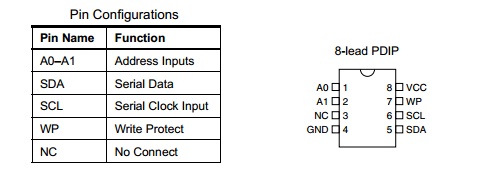
24C512 I2C EEPROM Pin Diagram
I2C Peripheral in STM32F4xx
STM32F407xx supports up to 3 I2C hardware modules inside it. Each of the three inbuilt I2C module are capable of providing full I2C capability. You can use any one them in your application, this example uses I2C1 to communicate with 24C512 EEPROM, you can similar kind of code and methods for I2C2 & I2C3. I2C in STM32F4 can also be used as SMBus (System Management Bus), but we will not discuss SMBus mode in this post.
I2C Main Features
- MultiMaster capability : the same interface can act as master or as slave.
- I2C Master is responsible for Clock generation (SCL) and start and stop generation
- I2C Slave is responsible for I2C Address detection, Stop bit detection.
- There are 2 Interrupts associated with I2C in STM32F4xx. 1 interrupt for successful address or data communication, 1 interrupt for error condition.
- 1 Byte buffer with DMA Capability , that means you can direct the data received over I2C to memory using DMA.
- Different clock speed operation with standard 100KHz operation or Fast mode 400KHz operation.
Ok, enough talks, Lets get straight to the Wiring and Code !
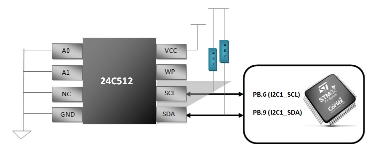
Wiring Diagram of STM32F4xx with 24C512
So, 24C512 is actually connected to PB.6 (I2C1_SCL) and PB.9 (I2C1_SDA) of STM32F4xx. 4.7K resistor are needed to pull up the I2C lines as these lines are Open drain by default. As you can see A0 and A1 are tied to ground to keep addressing as 0xA0 (Write Address) and 0xA1 (Read Addredd). If you are confused about how do i get these address value i ask you to read the datasheet of 24Cxx memory chips carefully. Now lets move onto the code part.
Function Level Abstraction
Though I am using I2C driver provided by ST microelectronics as a board support package, I have made three functions which are specific to I2C EEPROM Interfacing.
- init_I2C1(void); This function initializes the I2C hardware, all the I2C configuration are done in this function. Try to understand this function carefully (explained later in this post).
- uint8_t Write_24Cxx(uint16_t Addr, uint8_t Data, uint8_t Mem_Type); 16 bits variable is used for address because 24C512 accept address up to 0xffff, Others accept up to 0xff, this addressing scheme is taken care of in this function according to Mem_Type supplied by user. Mem_Type can be 24C01, 24C02, 24C04, 24C08, 24C16, 24C32, 24C64, 24C128, 24C256 & 24C512.
- uint8_t Read_24Cxx(uint16_t Addr, uint8_t Mem_Type); This is Memory read function, this function returns the 8 bit data read from Address ‘Addr’ of Memory ‘Mem_Type’.
void init_I2C1(void){
	GPIO_InitTypeDef GPIO_InitStruct; // this is for the GPIO pins used as I2C1SDA and I2C1SCL
	GPIO_InitTypeDef GPIO_Output;     // For some debugging LEDs
	I2C_InitTypeDef I2C_InitStruct; // this is for the I2C1 initilization
	/* enable APB1 peripheral clock for I2C1*/
	RCC_APB1PeriphClockCmd(RCC_APB1Periph_I2C1, ENABLE);
	/* enable the peripheral clock for the pins used by
	 PB6 for I2C SCL and PB9 for I2C1_SDL*/
        RCC_AHB1PeriphClockCmd(RCC_AHB1Periph_GPIOB, ENABLE);
	/* This sequence sets up the I2C1SDA and I2C1SCL pins
	 * so they work correctly with the I2C1 peripheral
	 */
	GPIO_InitStruct.GPIO_Pin = GPIO_Pin_6 | GPIO_Pin_9; // Pins 6(I2C1_SCL) and 9(I2C1_SDA)
	GPIO_InitStruct.GPIO_Mode = GPIO_Mode_AF; // the pins are configured as alternate function so the USART peripheral has access to them
	GPIO_InitStruct.GPIO_Speed = GPIO_Speed_2MHz;// this defines the IO speed and has nothing to do with the baudrate!
	GPIO_InitStruct.GPIO_OType = GPIO_OType_OD;// this defines the output type as open drain
	GPIO_InitStruct.GPIO_PuPd = GPIO_PuPd_UP;// this activates the pullup resistors on the IO pins
	GPIO_Init(GPIOB, &GPIO_InitStruct);// now all the values are passed to the GPIO_Init()
	RCC_AHB1PeriphClockCmd(RCC_AHB1Periph_GPIOD, ENABLE);
	 /* Configure PD12, PD13, PD14 and PD15 in output pushpull mode */
        GPIO_Output.GPIO_Pin = GPIO_Pin_12 | GPIO_Pin_13| GPIO_Pin_14| GPIO_Pin_15;
        GPIO_Output.GPIO_Mode = GPIO_Mode_OUT;
        GPIO_Output.GPIO_OType = GPIO_OType_PP;
        GPIO_Output.GPIO_Speed = GPIO_Speed_100MHz;
        GPIO_Output.GPIO_PuPd = GPIO_PuPd_NOPULL;
        GPIO_Init(GPIOD, &GPIO_Output);
	/* The I2C1_SCL and I2C1_SDA pins are now connected to their AF
	 * so that the I2C1 can take over control of the
	 * pins
	 */
	GPIO_PinAFConfig(GPIOB, GPIO_PinSource6, GPIO_AF_I2C1); //
	GPIO_PinAFConfig(GPIOB, GPIO_PinSource9, GPIO_AF_I2C1);
	 /* Configure I2C1 */
        I2C_DeInit(I2C1);
        /* Enable the I2C peripheral */
        I2C_Cmd(I2C1, ENABLE);
        /* Set the I2C structure parameters */
        I2C_InitStruct.I2C_Mode = I2C_Mode_I2C;
        I2C_InitStruct.I2C_DutyCycle = I2C_DutyCycle_2;
        I2C_InitStruct.I2C_OwnAddress1 = 0xEE;
        I2C_InitStruct.I2C_Ack = I2C_Ack_Enable;
        I2C_InitStruct.I2C_AcknowledgedAddress = I2C_AcknowledgedAddress_7bit;
        I2C_InitStruct.I2C_ClockSpeed = 30000;
        /* Initialize the I2C peripheral w/ selected parameters */
        I2C_Init(I2C1,&I2C_InitStruct);
}
There are a few lines worth explaining about init_I2C1() function. Line number 8, 12 & 14 initializes clocks for I2C1, GPIOB and GPIOD respectively, GPIOD is used to drive few LEDs connected to PD_12,13,14,15, these LEDs can be used to perform some debugging while rectifying errors in the code or can be used to indicate that certain operation was completed or gave an error.
Lines 48-53 configures the I2C1 hardware. It sets the Own Address of the device that can be used when this device acts as I2C Slave.
uint8_t Write_24Cxx(uint16_t Addr, uint8_t Data, uint8_t Mem_Type)
{
	uint32_t timeout = I2C_TIMEOUT_MAX;
	uint8_t upper_addr,lower_addr;
	lower_addr = (uint8_t)((0x00FF)&Addr);
	if(Mem_Type==M24512)
	{
	Addr = Addr>>8;
	upper_addr = (uint8_t)((0x00FF)&Addr);
        }
       /* Generate the Start Condition */
       I2C_GenerateSTART(I2C1, ENABLE);
       /* Test on I2C1 EV5, Start trnsmitted successfully and clear it */
       timeout = I2C_TIMEOUT_MAX; /* Initialize timeout value */
       while(!I2C_CheckEvent(I2C1, I2C_EVENT_MASTER_MODE_SELECT))
       {
            /* If the timeout delay is exeeded, exit with error code */
		if ((timeout--) == 0) return 0xFF;
       }
       /* Send Memory device slave Address for write */
       I2C_Send7bitAddress(I2C1, MEM_DEVICE_WRITE_ADDR, I2C_Direction_Transmitter);
       /* Test on I2C1 EV6 and clear it */
       timeout = I2C_TIMEOUT_MAX; /* Initialize timeout value */
       while(!I2C_CheckEvent(I2C1, I2C_EVENT_MASTER_TRANSMITTER_MODE_SELECTED))
       {
           /* If the timeout delay is exeeded, exit with error code */
		if ((timeout--) == 0) return 0xFF;
       }
	if(Mem_Type==M24512)
	{
		/* Send I2C1 location address LSB */
		I2C_SendData(I2C1, upper_addr);
		/* Test on I2C1 EV8 and clear it */
		timeout = I2C_TIMEOUT_MAX; /* Initialize timeout value */
		while(!I2C_CheckEvent(I2C1, I2C_EVENT_MASTER_BYTE_TRANSMITTED))
		{
			/* If the timeout delay is exeeded, exit with error code */
			if ((timeout--) == 0) return 0xFF;
		}
	}
	/* Send I2C1 location address LSB */
        I2C_SendData(I2C1, lower_addr);
      /* Test on I2C1 EV8 and clear it */
      timeout = I2C_TIMEOUT_MAX; /* Initialize timeout value */
      while(!I2C_CheckEvent(I2C1, I2C_EVENT_MASTER_BYTE_TRANSMITTED))
      {
            /* If the timeout delay is exeeded, exit with error code */
		if ((timeout--) == 0) return 0xFF;
      }
       /* Send Data */
       I2C_SendData(I2C1, Data);
        /* Test on I2C1 EV8 and clear it */
        timeout = I2C_TIMEOUT_MAX; /* Initialize timeout value */
        while(!I2C_CheckEvent(I2C1, I2C_EVENT_MASTER_BYTE_TRANSMITTED))
        {
             /* If the timeout delay is exeeded, exit with error code */
		if ((timeout--) == 0) return 0xFF;
        }
        /* Send I2C1 STOP Condition */
        I2C_GenerateSTOP(I2C1, ENABLE);
        /* If operation is OK, return 0 */
        return 0;
}
Code for Write_24Cxx is pretty much self explanatory. If you don’t get any part of it, you can ask in the comment below.
uint8_t Read_24Cxx(uint16_t Addr, uint8_t Mem_Type)
{
  uint32_t timeout = I2C_TIMEOUT_MAX;
  uint8_t Data = 0;
  uint8_t upper_addr,lower_addr;
  lower_addr = (uint8_t)((0x00FF)&Addr);
	if(Mem_Type==M24512)
	{
		Addr = Addr>>8;
		upper_addr = (uint8_t)((0x00FF)&Addr);
	}
  /* Generate the Start Condition */
  I2C_GenerateSTART(I2C1, ENABLE);
  /* Test on I2C1 EV5 and clear it */
  timeout = I2C_TIMEOUT_MAX; /* Initialize timeout value */
  while(!I2C_CheckEvent(I2C1, I2C_EVENT_MASTER_MODE_SELECT))
  {
    /* If the timeout delay is exceeded, exit with error code */
		if ((timeout--) == 0) return 0xFF;
  }
  I2C_Send7bitAddress(I2C1, MEM_DEVICE_WRITE_ADDR, I2C_Direction_Transmitter);
  /* Test on I2C1 EV6 and clear it */
  timeout = I2C_TIMEOUT_MAX; /* Initialize timeout value */
  while(!I2C_CheckEvent(I2C1, I2C_EVENT_MASTER_TRANSMITTER_MODE_SELECTED))
  {
    /* If the timeout delay is exeeded, exit with error code */
		if ((timeout--) == 0) return 0xFF;
  }
	if(Mem_Type==M24512)
	{
		/* Send I2C1 location address LSB */
		I2C_SendData(I2C1,upper_addr);
		/* Test on I2C1 EV8 and clear it */
		timeout = I2C_TIMEOUT_MAX; /* Initialize timeout value */
		while(!I2C_CheckEvent(I2C1, I2C_EVENT_MASTER_BYTE_TRANSMITTED))
		{
			/* If the timeout delay is exeeded, exit with error code */
			if ((timeout--) == 0) return 0xFF;
		}
	}
	  /* Send I2C1 location address LSB */
          I2C_SendData(I2C1, lower_addr);
          /* Test on I2C1 EV8 and clear it */
          timeout = I2C_TIMEOUT_MAX; /* Initialize timeout value */
          while(!I2C_CheckEvent(I2C1, I2C_EVENT_MASTER_BYTE_TRANSMITTED))
          {
               /* If the timeout delay is exeeded, exit with error code */
		if ((timeout--) == 0) return 0xFF;
          }
          /* Clear AF flag if arised */
          //I2C1->SR1 |= (uint16_t)0x0400;
          /* Generate the Start Condition */
          I2C_GenerateSTART(I2C1, ENABLE);
          /* Test on I2C1 EV6 and clear it */
          timeout = I2C_TIMEOUT_MAX; /* Initialize timeout value */
          while(!I2C_CheckEvent(I2C1, I2C_EVENT_MASTER_MODE_SELECT))
          {
               /* If the timeout delay is exeeded, exit with error code */
		if ((timeout--) == 0) return 0xFF;
          }
          I2C_Send7bitAddress(I2C1, MEM_DEVICE_READ_ADDR, I2C_Direction_Receiver);
          /* Test on I2C1 EV6 and clear it */
          timeout = I2C_TIMEOUT_MAX; /* Initialize timeout value */
          while(!I2C_CheckEvent(I2C1, I2C_EVENT_MASTER_RECEIVER_MODE_SELECTED))
          {
                /* If the timeout delay is exeeded, exit with error code */
		if ((timeout--) == 0) return 0xFF;
          }
          /* Prepare an NACK for the next data received */
          I2C_AcknowledgeConfig(I2C1, DISABLE);
          /* Test on I2C1 EV7 and clear it */
          timeout = I2C_TIMEOUT_MAX; /* Initialize timeout value */
          while(!I2C_CheckEvent(I2C1, I2C_EVENT_MASTER_BYTE_RECEIVED))
          {
                /* If the timeout delay is exeeded, exit with error code */
                 if ((timeout--) == 0) return 0xFF;
          }
          I2C_GenerateSTOP(I2C1, ENABLE);
          /* Receive the Data */
          Data = I2C_ReceiveData(I2C1);
          /* return the read data */
          return Data;
}
Write and Read functions follows the following waveform as shown in figure below…
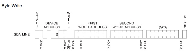
Single Byte Write Sequence
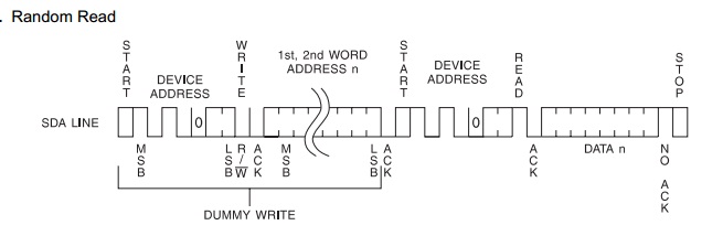
Random READ sequence follwed in Read_24Cxx Function
Example Usage
int main(void)
     {
  	int i;
        init_I2C1(); // initialize I2C1
	if(Write_24Cxx(0x0000,0x90,M2404))
	{
		//error
		while(1);
	}
	if((Read_24Cxx(0x0000,M2404))==0xff)
	{      // ERROR
		while(1)
		{
		        GPIO_ToggleBits(GPIOD, GPIO_Pin_12);
			GPIO_ToggleBits(GPIOD, GPIO_Pin_13);
			GPIO_ToggleBits(GPIOD, GPIO_Pin_14);
			Delay(0x05ffffff);
		}
	}
	else if((Read_24Cxx(0x0000,M2404))==0x90)
	{
		//Success
	}
        while (1)
        {
		        // Comes here in the end....
			GPIO_ToggleBits(GPIOD, GPIO_Pin_14);
			Delay(0x005fffff);
        }
    }
Download the Source code for this Example
Possible Future Improvements in this Library
- Add PAGE_READ, PAGE_WRITE functionality.
- Exploit the Continuous_Read and Continuous_Write chip functions. Right now reading/writing one BYTE at a time, these I2C EEPROM can be read/write continuously .
- Current Address READ function.