Getting Started with avr Prayog experiment board
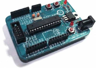 If you are reading this page, we assume that you have one avr prayog experiment board with you. If you do not have one, you can buy it at our main site http://electroons.com.
Preface
We are creating a series of Low cost but high quality development tools called 'Prayog'. In this process, our first design is Prayog with 28 Pin AVR devices, for example ATmega8, Mega88, Mega168, Mega328. This design is based on the idea of making a balance of features, that means Prayog boards are not make with all the peripherals on the experiment board itself, like we see in many development board. We call it Prayog experiment board (not development board) because our designs reflects true idea of experimentation. Most of the peripherals are not provided on board. You have to have a bread board with you and probably you are going to need a Soldering iron too. This is our way to make our board ultra low cost so that everyone can afford them.
At the same time we provide lots of Online support around these designs so that you can do your Prayog(experiment) easily and gain the confidence in your designs. Prayog experiment board designs are shared with you on the concept of Open Hardware. That means all the required stuff to make your own version of Prayog's are provided Open source, including the Interfacing codes, PCB Board files, Schematics and CAM files.
Features of Prayog Board - p28
- Elegant design
- Low cost
- Naming of all Pin functions on board
- Arduino Pin Mapping is also provided (to be explained later).
- Compatible to all 28 Pin AVR devices
- External male header expansion of all Pins of Micro controller.
- Can be used as Arduino with an Low cost add on shield (Overall cost (Prayog + Prayogduino) is lesser than actual arduino board )
- Handy to use, size is smaller than a Credit card.
- Completely open source, all schematics, boards, CAM files are distributed under Creative Commons attribution- NonCommercial 2.5 India License
How to use Prayog ?
Prayog board is designed in such a manner that, the user need not to refer to text/datasheets/pin-diagram/ again and again. We tried our best to provide the best possible amount of information on the board itself. All the pins, their special functions, regular functions are printed on the board itself, So once you become familiar to the Prayog board, you can work on it without looking at datasheets frequently. Sometimes you may require to refer to this Wiki or our site.
Going familiar with Prayog
- Power Supply : In bottom right corner of Prayog Board a DC Jack is provided to Plugin the Power source. You can plugin a DC Power source with voltage ratings of at least 7V and it can be up to 12V DC. Current rating of as low as 300mA should work fine, Power rating of your DC Power source depends on, what kind of Interfaces/ Peripherals are you running. when Power is OK RED LED will glow at bright intensity.
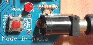
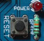
- RESET : Prayog board can be Reset to run from beginning of Program by pressing a Tactile button which is written RESET next to it on Prayog board.
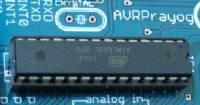
- 28 Pin avr device : Its heart of our experiment, this is what we are aiming to program and creating countless applications, projects and fun. It may be ATmega8, Mega88, Mega168 or Mega328. Prayog board can be programmed to use as Arduino. Tutorial on How to convert Prayog board into Arduino board will be following at PrayogWiki very soon.
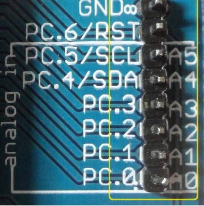
- All Pin expansion headers : All pins are provided to access externally for interfacing. Regular name of each pin as well as special function (e.g. RX/ TX, SDA, SCL) are printed on board itself. This rich naming convention make Prayog really easy to use, without a need of referring to datasheet frequently.
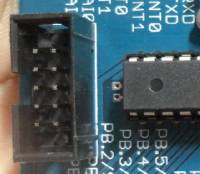
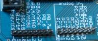
- Arduino PINs IO mapping : As said earlier Prayog can be used as Arduino (not yet shown how !), we have provided Arduino I/O Pins mapping printed on the board, all Digital IO pins from D0-D13 and Analog Inputs A0-A5 are marked on board. Please note that Prayog is not Physically compatible to Arduino, that means you can not plug in any Arduino Shield directly into Prayog. When i say that Prayog can be used as Arduino there i mean Logically not Physically. All Arduino pins are available on Prayog but not in same layout. You will get this concept of Logical compatibility once we write a Tutorial on using Prayog as Arduino.

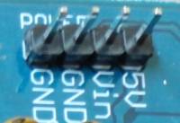
- Power supply headers expansion : Prayog board has 4 Pin Power Supply expansion header. It gives you direct access to Vin, +5V and 2 pins for Ground signal. where Vin the supply voltage you plugged in in the DC Jack.
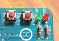
- Onboard LEDs and Tactile Switches : Two 3mm LEDs (1 red, 1 green) are provided on board, Can be used for debugging purposes. Green LED is connected to PORTD_0, that means 0th pin of PORTD, similarly RED LED is connected to PORTD_1 (1st pin of PORTD of avr). Two tactile switches are connected to PORTD_2 and PORTD_3 respectively. there is an important point to be noted here that PORTD_3 is also INT1 pin, so we can use Switch on PORTD_3 as trigger input to INT1 external interrupt, similarly PORTD_2 is INT0.
- Analog Channels: Prayog has 6 analog channels named as A0-A5 in the analog in section printed on board.
Next → == Doing your first Prayog (First Experiment) ==
— Prayog Boards by Devesh Samaiya are licensed under a Creative Commons Attribution-NonCommercial 2.5 India License.Based on a work at electroons.com.Permissions beyond the scope of this license may be available at http://electroons.com
