
Lonely Night Projects : DIY PMMC and Series Motor Model
— March 9, 2013Hi, Today i am going to demonstrate, How to make small motor models to learn the working of Permanent Magnet Moving Coil Type (PMMC) Motor and Series Coil Motor Model. The purpose of this experiment is to learn about the working principle of Small Motors, How Electromagnetic Induction comes to real life in such models.
Motors work on the principle of Electromagnetic Induction. It means, When a current carrying conductor is placed in a Magnetic Field, it experiences a longitudinal force, which can be used to generate rotatory motion. Various parameters are involved in this which determines the torque, speed, current etc for a particular design. Here we are not interested in all such detailed specification, Instead we are interested in the basic principle of working of Motor. So we are going to acquire a rotational force by using the law of electromagnetic induction.
Things Required !
Things required to perform this experiment are very easily available. You may find all the required stuff lying around in your house.
- Battery (I’ve used 6V SMF Lead Acid Battery, 1.5 Torch battery will also work)
- Insulated Copper Wire to make a Coil. (You may find lots of this wire from an Old small Transformer)
- A speaker Magnet (any old non operational, small Speaker can be used)
- Connecting Wires (Any electric wire used in household electric materials)
- Cello Tap
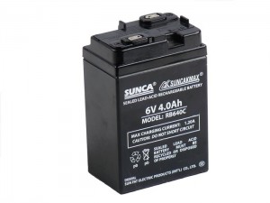
Battery
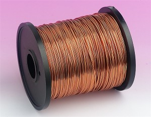
Enameled Copper Wire
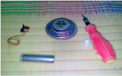
Required Stuff
Step 1 :
Take a Died AA battery Cell and use it to wound a coil as shown in the figure below. Remove the enameled copper wire from any old transformer and use AA battery as holder to make turns of coil. Make 12-15 turns only.
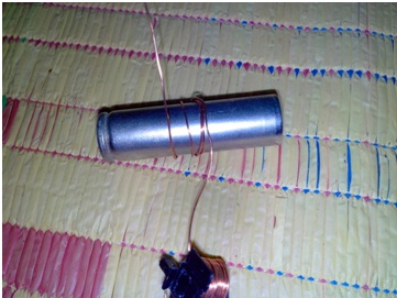
Use AA Battery to make a Coil
Step 2:
Now, remove the insulation from both sides of armature coil. You can use sand paper or any blade kind of thing to remove the insulation from the Copper wire. Exposed metal should be visible. If possible check with multi-meter if exposed ends from both sides are continuous (Connected). The exposed wire area should be around 1-2 centi meters away from the coil turns as shown in the picture. This exposed contacts will be used to make contacts with the stater.
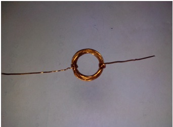
Armature with exposed metal from both the ends
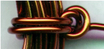
A close look at Enameled Copper Wire
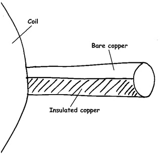
How insulation material is coated around bare copper wire
Step 3:
Remove the small permanent magnet from Speaker and cover it with transparent adhesive tap to ensure insulation.
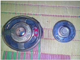
Backside of old dead Speaker
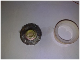
Insulate the magnet using any adhesive plastic tap
Step 4:
Now take another Enameled copper wire around 1 feet long. Bend the wire around the magnet as shown in figure and attach the wire with magnet using plastic adhesive tap, such that the whole assembly is hold tightly with each other.
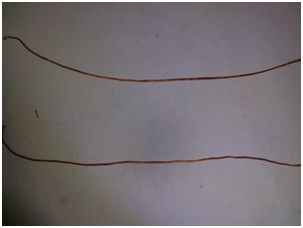
Take two enameled wires, each of around half feet
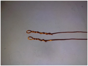
Bend the wire from both ends, these holes will hold the armature we built previously
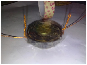
Attach it tightly with Magnet, use Cello tap for it
Step 5:
Now insert the rotor into the two loops of the magnet extension as shown. Make sure it can rotate on its axis freely.
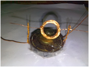
Final assembly of Rotor and Magnet
Step 6:
Now, solder the end of the wire and connect to the battery.
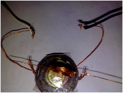
Solder the both ends of wires and connect it to the battery
and your PMMC motor is ready to ride. 
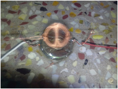
Rotating on its axis at very fast RPM
To be continued with DIY Series Coil motor…
About author


Leave a reply