
DIY PICkit2
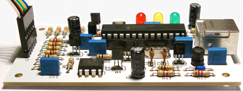
PICkit 2 was originally built by Microchip as open design programmer with the schematic, source code and firmware available to boost the popularity of the PIC devices. Because of that it is easy to build a clone version of the original device. Most of the clones will produce unregulated 5 volt VPP where the original Microchip PICkit 2 provides adjustable VPP output to allow 3.3 and 2.5 volt parts programming. The schematic I have used is based on the original PICkit 2 without programmer-to-go functionality. That functionality allowing a hex file to be downloaded to the PICkit 2 to later program PIC microcontrollers without a PC with a simple pressing programmer’s push button. I do not think that functionality is required for a hobbyist but allows simplify the schematic by omitting two 24C512 EEPROM chips. The Eagle Files designed using only thru-hole mounting parts.
For more details on DIY PICkit2 Programmer for PIC Microcontrollers [Link]
Comments & Responses
5 Responses so far.
Leave a Reply

Recent Posts
- Make In India - What it means to Indian Maker’s Community ?
- Breadboard Power Supplies - Read before you Buy One
- Product Review : Discover Wi-Fi extension board for stm32f4 discovery
- Product Review: OKI78SR-5/1.5 Switching Regulator from muRata Power Solutions
- Product Review - STM8S- Discovery by ST Microelectronics
- Know How : Using GSM Modem - Part 2/2
- Know How : Using GSM Modem - Part 1/2
- ST Microelectronics launches STM32 Nucleo Series
- SW18020P Vibration Switch Testing “Shake Switch”
- TCM8230MD Camera Breakout Board PCB, Can also mount AT45DB Series Flash Memory Chip
- IC Packages of Many Kinds - A comprehensive list
- Keil project setup for STM32F4 Discovery
- DIY - 12V 7.2Ah SMF Battery Charger Circuit
- Lonely Night Projects : DIY PMMC and Series Motor Model
- Toys from Trash with Arvind Gupta
- BodyCom Technology by Microchip for Embedded Security & Authentication
- Programmers for Atmel AVR Microcontrollers
- Nikola Tesla - The Greatest Inventor Ever Lived
- Crystal, Resonator and Oscillators, what’s the difference ?
- Pitfalls in STM32 Standard Peripheral Library & Possible Solutions
- Interrupt Driven UART Serial Communication for Atmel AVR
- DIY PICkit2
- What Thomas Edison expected job candidates to know !
- What does ‘AVR’ stands for ?
- Interfacing MCP4725, 12 bit DAC with AVR Microcontroller #avrPrayog
- Interfacing AT93C46 SPI EEPROM with avrPrayog
- How to recover the Unallocated space on Your SD card due to Raspberry Pi OS
- Driving an Alphanumeric LCD with avrPrayog
- Using Arduino/Freeduino as AVR ICSP Programmer
- DoCircuits : Turn your Web Browser into Prototyping Desk
Things You find here
- ADC Interfacing (1)
- Analog Design (4)
- Analog Designs (7)
- Arduino (9)
- ARM Microcontroller (12)
- ARM7 (6)
- Atmel AVR (8)
- Battery Chargers (2)
- Camera Interfacing (1)
- Display (1)
- EAGLE (3)
- EEPROM (2)
- Electrical Enginnering (6)
- Electronics (28)
- General Interest (15)
- General Know How (25)
- GSM Modem (2)
- Hello World (4)
- I2C (2)
- Interfacing Tutorial (15)
- Lonely Night Projects (4)
- LPC21xx (4)
- Make (4)
- mbed (1)
- Microchip (1)
- Microchip PIC (1)
- NXP (4)
- Open Source Ecology (2)
- Open Source Hardware (9)
- PCB Designing (2)
- Physical Computing (5)
- PIC Related (1)
- Power Supply (5)
- Product Review (2)
- Raspberry PI (1)
- Repair Tricks (2)
- SPI (2)
- ST Micro (8)
- STM32 (8)
- STM32F4 Doscovery (8)
- stm8 bit (1)
- Switch Mode Power supply (2)
- Technology (3)
- UART (3)
- Uncategorized (1)
Recently Said
- st1114g on How to recover the Unallocated space on Your SD card due to Raspberry Pi OS
- KpT, on How to recover the Unallocated space on Your SD card due to Raspberry Pi OS
- Neomanderx3 on I2C EEPROM Interfacing with STM32F4 Discovery
- Gábor on DIY PICkit2
- sapher on I2C EEPROM Interfacing with STM32F4 Discovery
- Tonino on DIY PICkit2
- nate on How to recover the Unallocated space on Your SD card due to Raspberry Pi OS
- mahd on TCM8230MD Camera Breakout Board PCB, Can also mount AT45DB Series Flash Memory Chip
- Andrew on How to recover the Unallocated space on Your SD card due to Raspberry Pi OS
- pavan on DIY - 12V 7.2Ah SMF Battery Charger Circuit
Trending Topic
Sponsored

 devesh[at]electroons[dot]com
 +91-9039-035-085

Sir,
Great job done. My self hobbyist and want to build PIC kit 2 programmer, but the circuit available in net mostly not clear enough either by schematic or some time they used some MOSFET not easily avilable.
Can you provide details of your hardware and firmware so that it can be built.
Thaks in advance
Regards,
Uttam Dutta
Sir,
Sorry I got the circuit after browsing your site
now I have 2 question
Did you check this programmer with all PIC families
I am not getting BAT85, can you suggest its equivalent diode.
Thanks in advance.
Please reply
Hi,
I have not tested it with all PICs, Since its a PICKit2 Clone it should do the Job as Original PIC Kit2.
Regarding BAT85 Substitute…
(nearly all the BAT family)
Bat41
Bat42
Bat43
Bat46
Bat47
Bat54
Bat86
1n5818
1n5819
Update us if you make this Clone yourself and What all PIC you test with it.
Thanks
Very good job.
Maybe you can help me to better understand some issues.
I have seen in many sites that a bootloader has to be programmed into the PIC18F2550 and then the PICKIT2 will programme/update the PIC with the firmware. The bootloader is not mentioned in your project.
Does the PK2V232000.HEX file contains the bootloader together with the firmware?
I have built a version of the PicKit2 lite and programmed the PIC18F2550 with that file (only). Windows does not recognize the USB device (unknown USB deviced detected) but when I press the button on the PicKit2 the red lights blinks (which i assume is a function of the bootloader).
Do I need to install a USB driver for windows?
thanks
Instead of 2N7000 can I use BS170?